
So my little arduino clone is fun but I was wondering something
-
They're labeled, but not in way that's helpful. Let me put it this way. The LCD is either the standard hitachi interface for it, just like the one the genuine arduino has, or it's just garbage because exactly one person knows how to use it and that's the person that designed it. if that's the case, no datasheet exists. So datasheets still aren't the solution.
Real programmers use butterflies
*SIGH* What a noob!
honey the codewitch wrote:
They're labeled, but not in way that's helpful.
You mean unmeaningful stuff like VSS, VDD, V0, RS, RW, E, D0 - D7? These don't tell you anything? Are you painting by numbers (= blindly following some examples)? VSS is the source voltage, or ground. VDD is your supply voltage (probably +5V). Mess these up and your display will be sending smoke signals and die. Check these. Vo, if I remember right, is not an input. It's a voltage that's produced in the display from the supply voltage. You are supposed to use a potentiometer to regulate the display's contrast. You should not take my word for it and check this in the datasheet. RS is a digital input to select one of two registers in the display. What are the registers for? Don't know, but you can always check the datasheet. In any case, you must make sure that only an output pin of the Arduino is connected here and is set to the correct value (0 or 1), depending on which register you want to access. RW is the read/write signal, oldschool 6800 style. 1 if you want to read the selected register and 0 if you want to write to it. A datasheet would tell you that. It's another input, so it must be hooked up to yet another output pin of the Arduino. E is the enable signal, also old 6800 style. It's also an input, so you will need another output pin from the Arduino here. D0 - D7 are your eight data bits. You will need eight bidirectional signals from the Arduino, or if it does not have such data lines, reconfigure these I/O pins to the right direction for every access of the display. Here you can easily send both the Arduino and the display to east hyperspace when you read from the display and the Arduino's I/O pins are still set to be outputs. Here you should read up on how the Arduino handles bidirectional parralel data lines and make sure that such a collision never happens. Short two outputs together and you get a nice short circuit which will fry a few transistors and permanently damage your devices. A and K are simple. They are the anode and cathode of the LED that lights the display. You only need to hook them up to +5V and ground with a resistor to limit the current. Which value? Ask the data sheet. It will tell you the maximum current that is allowed and Ohm's law will tell you the rest. Just guessing, but a typical single LED works nicely with a 470 Ohm resistor in series. I have some that survived more than 40 years that way.
-
*SIGH* What a noob!
honey the codewitch wrote:
They're labeled, but not in way that's helpful.
You mean unmeaningful stuff like VSS, VDD, V0, RS, RW, E, D0 - D7? These don't tell you anything? Are you painting by numbers (= blindly following some examples)? VSS is the source voltage, or ground. VDD is your supply voltage (probably +5V). Mess these up and your display will be sending smoke signals and die. Check these. Vo, if I remember right, is not an input. It's a voltage that's produced in the display from the supply voltage. You are supposed to use a potentiometer to regulate the display's contrast. You should not take my word for it and check this in the datasheet. RS is a digital input to select one of two registers in the display. What are the registers for? Don't know, but you can always check the datasheet. In any case, you must make sure that only an output pin of the Arduino is connected here and is set to the correct value (0 or 1), depending on which register you want to access. RW is the read/write signal, oldschool 6800 style. 1 if you want to read the selected register and 0 if you want to write to it. A datasheet would tell you that. It's another input, so it must be hooked up to yet another output pin of the Arduino. E is the enable signal, also old 6800 style. It's also an input, so you will need another output pin from the Arduino here. D0 - D7 are your eight data bits. You will need eight bidirectional signals from the Arduino, or if it does not have such data lines, reconfigure these I/O pins to the right direction for every access of the display. Here you can easily send both the Arduino and the display to east hyperspace when you read from the display and the Arduino's I/O pins are still set to be outputs. Here you should read up on how the Arduino handles bidirectional parralel data lines and make sure that such a collision never happens. Short two outputs together and you get a nice short circuit which will fry a few transistors and permanently damage your devices. A and K are simple. They are the anode and cathode of the LED that lights the display. You only need to hook them up to +5V and ground with a resistor to limit the current. Which value? Ask the data sheet. It will tell you the maximum current that is allowed and Ohm's law will tell you the rest. Just guessing, but a typical single LED works nicely with a 470 Ohm resistor in series. I have some that survived more than 40 years that way.
A lot of that jibes with what the schematic suggested. I think you're right about V0 for example. The short answer is no, I don't know what I'm doing. I used to build simple circuits when I was little. After that I took up programming. I've never taken classes or read books about this. Eventually I got this Arduino and here I am. So I'm learning. *steps off your lawn*
Real programmers use butterflies
-
If you had the resistor in place from the start, that strongly reduces the probability you wrecked the display; so either it was broken already, or it is still OK and your observations are flawed. I did mention the existence of the separate I2C convertor, I did not intend that as a suggestion; when in doubt about the state of the current display, maybe just replacing it is a better idea than adding to it. Or doing some more tests: If you connect the current display, you could try writing and reading its registers, even when no crystals are seen moving. First step though would be to check the power pins (you have ordered a multimeter by now I hope), a resistor plus a LED could suffice to check anything is present between the GND and 5V pins. :)
Luc Pattyn [My Articles] If you can't find it on YouTube try TikTok...
Yes I have ordered one. And I can by with an LED+resistor for now. Someone else gave me a good breakdown of what the pins did. Seemed maybe I frustrated them for being a noob :laugh: , but at least I learned something.
Real programmers use butterflies
-
A lot of that jibes with what the schematic suggested. I think you're right about V0 for example. The short answer is no, I don't know what I'm doing. I used to build simple circuits when I was little. After that I took up programming. I've never taken classes or read books about this. Eventually I got this Arduino and here I am. So I'm learning. *steps off your lawn*
Real programmers use butterflies
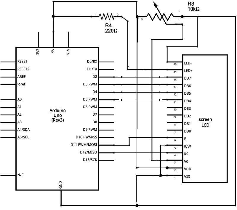
Ok, let's try it a different way, then. I assume you use a small breadboard to wire everything up. Ignore the wiring guide for the breadboard. Use a schematic instead, like this one[^]. I hope this is the right one, please check that. First you should understand howw to use a breadboard[^]. It's not really hard to understand, but you do not want to produce shorts or unwanted connections. First you hook up the voltages. VSS or GND are ground, VCC, VDD or +5V are typically supply voltages. V0 is a special voltage that is provided by the display. It's an output, not an input, so you do not have to worry about it right now. You must be very careful with voltages. You can really fry your hardware when they are reversed. Double and triple check everything before ever switching it on. Now you can take care of the backlight. Here you can do less harm, but you have the additional complication of having to use external potis and resistors. Just follow the schematic and check your wiring then it will be ok. The A and K signals might also be labled as LED+ and LED-. RW is simply tied to ground (aka VSS). That means you can only write to the display and not read anything. That's good, because this way the display will never use D0 - D7 as outputs and a collision with the Arduino's I/O pins is impossible. The Arduino does not have the old 6800 bus signals. It's a microcontroller that has to emulate these signals on its general I/O pins. Let's assume for now that the little software library you have does this correctly. On the hardware side it's relatively simple. You must hook up the right Arduino signal to the right signal of the display, as shown in the schematic. On the Arduino side you will have signals named D0 - D(whatever). These are the general I/O pins. They have nothing to do directly with D0 - D7 on the display. Don't confuse them. They are different signals that just happen to use similar naming conventions. Just follow the schematic and the labels on the connectors. Do not go by pin numbers, because they may not be as standardized as we would like them to be. Once you have wired up the display's RS, E
-
Ok, let's try it a different way, then. I assume you use a small breadboard to wire everything up. Ignore the wiring guide for the breadboard. Use a schematic instead, like this one[^]. I hope this is the right one, please check that. First you should understand howw to use a breadboard[^]. It's not really hard to understand, but you do not want to produce shorts or unwanted connections. First you hook up the voltages. VSS or GND are ground, VCC, VDD or +5V are typically supply voltages. V0 is a special voltage that is provided by the display. It's an output, not an input, so you do not have to worry about it right now. You must be very careful with voltages. You can really fry your hardware when they are reversed. Double and triple check everything before ever switching it on. Now you can take care of the backlight. Here you can do less harm, but you have the additional complication of having to use external potis and resistors. Just follow the schematic and check your wiring then it will be ok. The A and K signals might also be labled as LED+ and LED-. RW is simply tied to ground (aka VSS). That means you can only write to the display and not read anything. That's good, because this way the display will never use D0 - D7 as outputs and a collision with the Arduino's I/O pins is impossible. The Arduino does not have the old 6800 bus signals. It's a microcontroller that has to emulate these signals on its general I/O pins. Let's assume for now that the little software library you have does this correctly. On the hardware side it's relatively simple. You must hook up the right Arduino signal to the right signal of the display, as shown in the schematic. On the Arduino side you will have signals named D0 - D(whatever). These are the general I/O pins. They have nothing to do directly with D0 - D7 on the display. Don't confuse them. They are different signals that just happen to use similar naming conventions. Just follow the schematic and the labels on the connectors. Do not go by pin numbers, because they may not be as standardized as we would like them to be. Once you have wired up the display's RS, E
Thank you! This is even more than enough information for me to tinker with. I greatly appreciate it.
Real programmers use butterflies
-
Thank you! This is even more than enough information for me to tinker with. I greatly appreciate it.
Real programmers use butterflies
I don't want to spoil your fun, but this is not playing with Lego and it will never be. It's programming and you know how far cut and paste solutions will get you. The real trophy here is not getting that display to work. It's learning why it does not work right now and learning from it. You should know how addictive that can get once you get a taste of accomplishment. Just ask Tom Hanks[^]. :-)
I have lived with several Zen masters - all of them were cats. His last invention was an evil Lasagna. It didn't kill anyone, and it actually tasted pretty good.
-
I don't want to spoil your fun, but this is not playing with Lego and it will never be. It's programming and you know how far cut and paste solutions will get you. The real trophy here is not getting that display to work. It's learning why it does not work right now and learning from it. You should know how addictive that can get once you get a taste of accomplishment. Just ask Tom Hanks[^]. :-)
I have lived with several Zen masters - all of them were cats. His last invention was an evil Lasagna. It didn't kill anyone, and it actually tasted pretty good.
I'm not doing cut and paste solutions. I'm learning. There's a difference. Understand the difference. Edit: I'm not done. If I wanted a copy and paste solution I would have asked someone for that. I never did. I asked about a way to test a device i suspected i broke (or came broke) for signs of life. If anything I'm debugging. I did not ask you to develop a monitor for my father in law's pump house. If I had wanted a cut and paste solution I would have asked for that. Instead, you didn't even know what I was building. I don't know where you got that, and frankly, it was offensive. I am working with a kit that came with no instructions, no labels, and in an area where I haven't had any practice since 1986 when i was a small child. I've already build several working widgets with this. I just wanted to know a way to figure out if I broke the LCD or not. That's all I was asking for. Sincerely, thank you for you help with that. But you can keep your most recent comment.
Real programmers use butterflies
-
Does anyone know what the simplest circuit to use for a 16 pin LCD hitachi style display is to make it display *anything* or even turn on the backlight? I got a new kit and I can't seem to get the LCD display to respond at all, and I'm not finding the answer to this anywhere. All the examples I can find use a library, and require the thing to be fully wired up. The problem is, after having done that, even after double checking and triple checking my wiring against the examples it still didn't work. I need something simpler just to do a basic power-on sanity check for the LCD. I have no idea what the hitachi display protocol looks like in practice and the pins aren't very descriptive. I know there are some arduino-heads here on CP. Can I get that LCD to do anything at all with two or three connections?
Real programmers use butterflies
Hi i've only just just been playing with a 16 pin LCD1602 display on my raspberry pi yesterday, and im connecting it via I2C as it only needs 2 wires (+ gnd & 5v) but i do know you need I2C and SPI enabled for it to work. i use an adafruit python library, and it's all is pretty simple. i dont know arduino boards or how to do this on them, but maybe this snippet of info will help - btw i watched a few youtube video's for tutorials. GL
-
That's interesting. I wouldn't know since this kit has zero instructions. It's a clone of the Arduino Mega 2560 and presumably all of the gear in the kit (like the display) is supposed to work out of the box just like the arduino stuff. If not, then I may as well throw it away since there are no instructions. That said, the pinouts for this LCD and the one in the Arduino provided sample are all labeled the same except 2 pins have a different name on the schematic - "A" vs "LED+" and "K" vs "LED-" but i think they are the same thing, given the other 14 pins are identical, and those are for the backlight according to the schematic
Real programmers use butterflies
K=kathode/-, A=anode/+; so indeed a generalisation of LED-/LED+.
-
Does anyone know what the simplest circuit to use for a 16 pin LCD hitachi style display is to make it display *anything* or even turn on the backlight? I got a new kit and I can't seem to get the LCD display to respond at all, and I'm not finding the answer to this anywhere. All the examples I can find use a library, and require the thing to be fully wired up. The problem is, after having done that, even after double checking and triple checking my wiring against the examples it still didn't work. I need something simpler just to do a basic power-on sanity check for the LCD. I have no idea what the hitachi display protocol looks like in practice and the pins aren't very descriptive. I know there are some arduino-heads here on CP. Can I get that LCD to do anything at all with two or three connections?
Real programmers use butterflies
I haven't messed with the hitachi screens. can you give a PN/model to look at the docs? usually not all pins are used, with the screens I've worked with in the past, based off of memory: 7 pins for the command byte 1 CTS 1 power for lcd cpu 1 power for back light (not usually crossed over as this pin can be PWM for dimming) 1+ grounds 1 reset - can sometimes be ignored, depending on the model. sometimes necessary on boot. are you using a pre-made driver library? you will ether have to use their pin set up or configure the setup in the header file. if you are trying to roll your own, it not too difficult, but sometimes finding the documentation in English can be rather difficult. there are usually a sequence of bytes that have to be sent to the LCD at startup to initialize them. then a 10 to 20ms for the LCD to be ready for commands. some pins may require to switch I/O status to report something back to the driver. not all LCDs are 5v, many of them are the 3.3v on the logic side and would require a level shifter, but the backlight may still be 5v If I have the choice in the future, I'd rather go with the I2C interface to save a lot of pins I know of quite a few gotcha's in the back of my head, but it's been a few years since I've messed with LCD's and I haven't had my morning coffee yet.
-
Got it new off amazon. Only concern is it is a knockoff made my elegoo and not an arduino branded kit. It was a lot cheaper so if i have to order a replacement LCD screen I'm probably still money ahead. :) Although that's not taking into account the aggravation of testing an LCD screen for signs of life.
Real programmers use butterflies
If it's elegoo then really don't worry, they are one of the better ones, and consistantly much of thier gear is of really high quality. I have a number of elegoo products, and to date I've never had a problem with any of them. In fact I find the cheep bundled Arduino Uno clones are often better constructed than the original ones and half the price!
-
Does anyone know what the simplest circuit to use for a 16 pin LCD hitachi style display is to make it display *anything* or even turn on the backlight? I got a new kit and I can't seem to get the LCD display to respond at all, and I'm not finding the answer to this anywhere. All the examples I can find use a library, and require the thing to be fully wired up. The problem is, after having done that, even after double checking and triple checking my wiring against the examples it still didn't work. I need something simpler just to do a basic power-on sanity check for the LCD. I have no idea what the hitachi display protocol looks like in practice and the pins aren't very descriptive. I know there are some arduino-heads here on CP. Can I get that LCD to do anything at all with two or three connections?
Real programmers use butterflies
Whenever you work with something like this, always look for the "Data Sheet" they are the source of all truth no matter what any user guides you get with the product say. In your case, this is the one you need: [https://www.sparkfun.com/datasheets/LCD/HD44780.pdf\](https://www.sparkfun.com/datasheets/LCD/HD44780.pdf) The HD44780 is the driver chip (Probably under a blob of black rubber) on the back of the display, and 99.9% of all this types of display use that driver chip. Even the 3 wire I2C ones use that driver chip, they just put a multi port I2C GPOI chip (Such as an MCP23017) in front of the Hitachi one and take care of the pin handling for you. The wiring you need for the display will look something like this: (https://hacksterio.s3.amazonaws.com/uploads/attachments/1138784/basic\_lcd\_control\_B4wegmYYMt.png) That diagram is wired for "4 bit mode", these displays can be wired up to work in either 4 or 8 bit mode (The former is to save some connecting wires) in 4 bit mode you have to make 2 writes to the display to send a full byte, otherwise the programming commands (Values of the bytes sent) are identical between both modes. Also pay close attention to those pre made boards you get with the kits, they are often wired from right to left, rather than left to right. This means that "Bit 0" of your 4 or 8 data pins is actually right most (Like in the diagram above) and bit 7 is left most. Once you have your power hooked up, and your data lines, you need to pay close attention tot he 3 lines marked 'RS', 'R/W' and 'E' The RS line is called register select and is toggled to a 1 or a 0 depending on what your sending to the display. If your sending a command byte (as described in the data sheet) EG: enable display, turn cursor on/off, set 4/8 bit mode etc then you need to be sending 0v on this line BEFORE you write the command byte. If your sending a byte of data EG: a letter to display on the LCD, then 'RS' MUST be set to +5V Your R/W line is the "Read NOT write line", pay close attention tot he fact that there is a vertical bar drawn over the top of the letter. This vertical bar means that the signal is what's called "Active Low", or in laymans terms "it does something when it's held at 0v", in our case when the signal is "High" (+5v logic) then the signal tells the device to be in "Read Mode" for all of the 8 data bus lines, and when it's "NOT write" it's in write mode. Why does this display have a read mode? Well LCD displays using this chip can read the letters entered
-
Does anyone know what the simplest circuit to use for a 16 pin LCD hitachi style display is to make it display *anything* or even turn on the backlight? I got a new kit and I can't seem to get the LCD display to respond at all, and I'm not finding the answer to this anywhere. All the examples I can find use a library, and require the thing to be fully wired up. The problem is, after having done that, even after double checking and triple checking my wiring against the examples it still didn't work. I need something simpler just to do a basic power-on sanity check for the LCD. I have no idea what the hitachi display protocol looks like in practice and the pins aren't very descriptive. I know there are some arduino-heads here on CP. Can I get that LCD to do anything at all with two or three connections?
Real programmers use butterflies
Assuming it's protocol compatible with HD44780, hardwiring the command 0b00001111 and then toggling the clock/enable bit should turn the display on, show the cursor, and make the cursor blink. Also, make sure RS & R/W are set to 0/GND, obviously VCC and GND are connected, and the backlight power is connected, if applicable (pins 15/16). Of course, the assumes it powers on in 8-bit mode. If it powers up in 4-bit mode, it becomes messier. This wikipedia page gives a command sequence that will ensure the mode is consistent: Hitachi HD44780 LCD controller. Note: I haven't actually tried this, but based on the wiki and datasheet, it should be the minimum needed to wire up (if manually toggling the clock with a button or wire touch, no arduino needed).
-
Does anyone know what the simplest circuit to use for a 16 pin LCD hitachi style display is to make it display *anything* or even turn on the backlight? I got a new kit and I can't seem to get the LCD display to respond at all, and I'm not finding the answer to this anywhere. All the examples I can find use a library, and require the thing to be fully wired up. The problem is, after having done that, even after double checking and triple checking my wiring against the examples it still didn't work. I need something simpler just to do a basic power-on sanity check for the LCD. I have no idea what the hitachi display protocol looks like in practice and the pins aren't very descriptive. I know there are some arduino-heads here on CP. Can I get that LCD to do anything at all with two or three connections?
Real programmers use butterflies
Hi honey the LCDwitch :-D any progress? I just happen to be working on a PIC+LCD project; my LCD is working, after some struggle, and here are my recent observations: 1. pin 3 is most relevant; a lot of documentation is misleading, this pin is not "LCD power" or some similar, suggesting 5V would be reasonable. It is a contrast control input, the official approach is using a little potmeter, say 10K, between GND and 5V, and turning it very close to ground, NOT close to 5V. A good alternative seems to be just a diode from pin 3 to GND; that is what I'm using now. 2. The LCD needs a few commands to become alive; one of them is the "function set" command, holding a "display ON" bit; so you need some correct toggling of E, RS, and 4 or 8 data lines. 3. The pulses required on E are a bit special: the leading edge must fall after RS and RW have settled, and the falling edge after the data is presented. This is unlike most other micro-electronic peripherals I have ever seen (normally one edge is used to sample everything, and the other edge doesn't care much). 4. The data bus is either 8 or 4 bits wide; in order to get it in 4-bit mode RELIABLY you need a specific sequence of commands. Without proper initialization the display remains blank, as if no power were applied. And the display may remain confused as long as it is getting power (or a really correct command sequence).What Hitachi HD44780 LCD controller - Wikipedia[^] says is correct and effective, it is better then what a lot of data sheets provide! Some manufacturers that used to provide bad info are now refraining from providing initialization info at all. The mistakes can be blatant or subtle, I also found a github code sample that was wrong... This is what I'm using right now (using a 4-bit interface):
CALL WAIT40msec ; important! BCF LCD\_RS\_PP ; set RS low MOVLW 0x03 ; 8-bit interface CALL display\_write\_nibble CALL WAIT1msec MOVLW 0x03 ; 8-bit interface CALL display\_write\_nibble CALL WAIT1msec MOVLW 0x03 ; 8-bit interface CALL display\_write\_nibble CALL WAIT1msec MOVLW 0x02 ; 4-bit interface CALL display\_write\_nibble CALL WAIT60usec MOVLW 0x28 ; 4-bit interface, single line, 5\*8 font CALL display\_send\_fast\_command MOVLW 0x08 ; display off CALL display\_send\_fast\_command MOVLW 0x01 ; clear CA -
Hi honey the LCDwitch :-D any progress? I just happen to be working on a PIC+LCD project; my LCD is working, after some struggle, and here are my recent observations: 1. pin 3 is most relevant; a lot of documentation is misleading, this pin is not "LCD power" or some similar, suggesting 5V would be reasonable. It is a contrast control input, the official approach is using a little potmeter, say 10K, between GND and 5V, and turning it very close to ground, NOT close to 5V. A good alternative seems to be just a diode from pin 3 to GND; that is what I'm using now. 2. The LCD needs a few commands to become alive; one of them is the "function set" command, holding a "display ON" bit; so you need some correct toggling of E, RS, and 4 or 8 data lines. 3. The pulses required on E are a bit special: the leading edge must fall after RS and RW have settled, and the falling edge after the data is presented. This is unlike most other micro-electronic peripherals I have ever seen (normally one edge is used to sample everything, and the other edge doesn't care much). 4. The data bus is either 8 or 4 bits wide; in order to get it in 4-bit mode RELIABLY you need a specific sequence of commands. Without proper initialization the display remains blank, as if no power were applied. And the display may remain confused as long as it is getting power (or a really correct command sequence).What Hitachi HD44780 LCD controller - Wikipedia[^] says is correct and effective, it is better then what a lot of data sheets provide! Some manufacturers that used to provide bad info are now refraining from providing initialization info at all. The mistakes can be blatant or subtle, I also found a github code sample that was wrong... This is what I'm using right now (using a 4-bit interface):
CALL WAIT40msec ; important! BCF LCD\_RS\_PP ; set RS low MOVLW 0x03 ; 8-bit interface CALL display\_write\_nibble CALL WAIT1msec MOVLW 0x03 ; 8-bit interface CALL display\_write\_nibble CALL WAIT1msec MOVLW 0x03 ; 8-bit interface CALL display\_write\_nibble CALL WAIT1msec MOVLW 0x02 ; 4-bit interface CALL display\_write\_nibble CALL WAIT60usec MOVLW 0x28 ; 4-bit interface, single line, 5\*8 font CALL display\_send\_fast\_command MOVLW 0x08 ; display off CALL display\_send\_fast\_command MOVLW 0x01 ; clear CAI've decided to move to displays that are SPI or I2C based. It's just too many wires and i don't like putting pots in my circuits, and all that. it's just a mess and I'd rather go with something cleaner. Thanks though. I do have that display still but it's collecting dust. =)
Real programmers use butterflies